Precision at the Cutting Edge
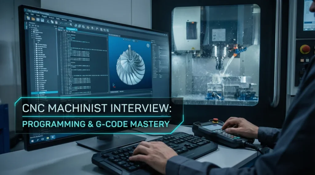
The CNC Machinist is the skilled artisan of the modern industrial age, blending computer programming logic with the physical intuition of a master craftsman. You are the person who takes a block of raw titanium or aluminum and transforms it into a flight critical aerospace component or a life saving medical implant, holding tolerances thinner than a human hair. Hiring managers are looking for candidates who can do more than just push the green button; they need problem solvers who can interpret complex G-code, optimize tool paths to shave seconds off cycle times, and troubleshoot chatter before it scraps a ten thousand dollar part. This guide covers cnc machinist interview questions that span from basic setup procedures to advanced multi-axis programming strategies, designed to prove you are the technical expert they need on the shop floor.
G-Code & Programming Logic
Q: Explain the difference between G00, G01, G02, and G03 codes.
These are the fundamental motion commands that drive the machine’s movement. G00 is “Rapid Positioning,” used to move the tool as fast as possible through the air to get to the start point or retract to a safe position. It never cuts material because the machine moves at maximum velocity, often in a non linear dogleg path, which would destroy the part or the tool if it engaged the stock.
G01 is “Linear Interpolation,” the primary cutting code. It moves the tool in a perfectly straight line from point A to point B at a specified Feed Rate (F). G02 and G03 are for circular interpolation, cutting arcs. G02 cuts a clockwise arc, while G03 cuts a counter clockwise arc. Mastering these is essential because even if you use CAM software, you must be able to read the code at the machine to verify the path, debug a program, or edit a chamfer manually at the control.
Q: What is a “Canned Cycle” and why do we use them?
A Canned Cycle (like G81 for drilling, G83 for peck drilling, or G84 for tapping) is a pre programmed macro stored in the machine’s controller that simplifies programming complex repetitive operations. Instead of writing every single Z-axis move down to cut, up to retract, and back down again for a deep hole, I write one line of code that tells the machine: “Drill at this X/Y location, to this Z depth, with this peck increment (Q), and retract to this clearance plane (R).”
We use them primarily to save memory and drastically reduce programming time. It also makes the code far easier to read and edit on the shop floor. If I need to change the peck depth to break chips better because the material is stringy, I only have to change the “Q” value in one line of code, rather than rewriting hundreds of lines of linear moves. This reduces the chance of typing errors that could cause a crash.
Q: How do you use G41 and G42 Cutter Compensation?
Cutter Compensation allows me to program the actual geometry of the part (the blue line on the print) rather than calculating the path of the center line of the tool. G41 is “Cutter Compensation Left” (used for climb milling), and G42 is “Cutter Compensation Right” (used for conventional milling). When active, the machine automatically calculates the offset path based on the tool diameter stored in the geometry offset table.
This feature is critical for holding tight tolerances in a production environment. If a 0.500 inch endmill wears down to 0.498 inch after cutting 50 parts, I don’t have to go back to the CAM software and repost the program. I simply update the tool diameter in the machine’s offset page to 0.498, and the controller automatically adjusts the tool path inward by 0.001 inch per side to keep the part size perfect. It gives the machinist control over the final dimension without changing the code.
Q: What is the difference between Absolute (G90) and Incremental (G91) positioning?
G90 (Absolute) means all coordinates are measured from a fixed, single origin point (the Work Offset like G54, X0 Y0). If I command “X10.0”, the tool moves to the position exactly 10 inches from the part zero. This is the safest and most common mode because the tool’s position is always known relative to the part datum.
G91 (Incremental) means coordinates are measured from the current position of the tool. If I command “X10.0”, the tool moves 10 inches to the right from wherever it happens to be standing at that moment. I mostly use G90 for the main program for safety, but G91 is extremely useful for subroutines, such as drilling a grid of holes where the spacing is identical, or for loop commands where I want to repeat a cutting motion multiple times at different depths.
Machine Setup & Tooling
Q: Walk me through how you touch off tools and set Work Offsets (G54).
To set the Work Offset (X, Y), which defines where the part is located on the table, I use an edge finder or a Renishaw probe. I spin the edge finder at 1000 RPM and locate the edges of the stock or the precision ground datum of the vise. When the edge finder kicks over, I account for the radius (usually 0.100 inch) and set those coordinate values into the G54 register. This tells the machine exactly where the part zero is in relation to the machine home.
To set Tool Length Offsets (H values), I use an offline tool presetter if available, or touch off inside the machine using a 1-2-3 block or the probe’s tool setter stylus. I measure the distance from the spindle gauge line to the tool tip. Accurate tool lengths are non negotiable; a bad length offset is the most common cause of machine crashes. I always double check my “Distance to Go” on the first approach to verify the offset is correct before the tool touches the part.
Q: How do you select the correct Feeds and Speeds for a new material?
I start with the scientific data from the tool manufacturer’s catalog, which gives the recommended Surface Feet Per Minute (SFM) and Chip Load (Inches Per Tooth – IPT) for the specific material group (e.g., P-Steels, M-Stainless, K-Cast Iron). I use the formula: RPM = (SFM x 3.82) / Tool Diameter. Then I calculate the Feed Rate: IPM = RPM x Number of Flutes x Chip Load.
However, the textbook numbers are just a starting point. I adjust based on the rigidity of the setup. If the part is thin walled, or the tool stick out is long (causing potential vibration), I reduce the speed and feed to prevent chatter. If I am cutting a hard superalloy like Inconel or Hastelloy, I slow the SFM way down to generate less heat and preserve tool life. It is a balance between the physics of the cutting edge and the reality of the workholding.
Q: What is the difference between Climb Milling and Conventional Milling?
Climb Milling (Down Milling) is when the tool rotates into the cut in the direction of feed, creating a thick-to-thin chip. The cutter tries to “climb” over the material. It pulls the work piece firmly down into the fixture and leaves a superior surface finish because the chip exits cleanly behind the cut. It is the industry standard for modern CNCs equipped with zero backlash ballscrews and rigid ways.
Conventional Milling (Up Milling) rotates against the feed, creating a thin-to-thick chip. It tends to push the tool away from the part and lift the work piece up. I only use it in specific situations: when machining rough castings with a hard abrasive skin (scale) to cut from the inside out, or on old manual machines with significant backlash, to keep the lead screw loaded. Using it unnecessarily causes heat buildup and rapid tool wear.
Q: How do you prevent “Chatter” during machining?
Chatter is a self excited regenerative vibration that ruins the surface finish and destroys cutting edges. My first fix is to change the RPM to break the harmonic resonance; often, speeding up or slowing down by 10 percent eliminates the vibration. Second, I look at the tool assembly – is the gauge length (stick out) too long? Rigidity drops by the cube of the length, so shortening the tool by even half an inch makes a massive difference.
If those quick fixes don’t work, I look at the process. I might increase the feed rate slightly to stabilize the cut (put more constant load on the tool) or switch to a high performance endmill with a variable helix angle designed to disrupt harmonics. Checking the fixture rigidity is also key; a part that is vibrating in the jaws will always chatter, no matter what speeds you run.
Q: Describe your process for machining the first side of a raw casting.
Machining the first side (Op 10) is the most difficult because there are no flat, true datums to locate from. I usually clamp the raw casting in a 4 jaw independent chuck (for lathes) or use toe clamps/vise with serrated jaws that bite into the raw stock (for mills). I use a floating stop or shims to support the uneven surface so I don’t bend the casting when I tighten the clamps.
I take light facing cuts initially to establish a flat “qualification” surface without pulling the part out of the jaws with heavy cutting forces. Once I have created a flat face and a reference edge, the subsequent operations (Op 20, 30) become much easier and more precise because I can locate off the machined surfaces. The goal of Op 10 is not finish; it is establishing geometry.
Q: How do you bore a hole to a 0.0005 inch tolerance?
I drill the hole slightly undersize first to remove the bulk of the material, then use an endmill to circular interpolate (or a reamer) to get the hole straight and round, leaving about 0.010 inch of stock per side. For the final finish pass, I use a single point precision boring head, which gives the best geometric roundness.
I take a test cut, stop the spindle, and measure the hole with a calibrated bore gauge or air gauge. I then adjust the boring head dial (often graduated in tenths of a thousandth) to sneak up on the final size. I factor in thermal expansion – a warm part will shrink when it cools, so I aim for the upper limit of the tolerance to ensure it stays in spec once it reaches room temperature.
Troubleshooting & Quality
You are running a production job and the parts suddenly start measuring 0.002 inches oversized. What do you do?
I stop the machine immediately. I check the cutting tool first – is it worn, or has a “built up edge” of aluminum welded to the tip? A dull tool pushes away from the cut, causing oversize parts. If the tool looks good, I check the machine temperature – did we just come back from lunch and the machine cooled down? Thermal growth is a common culprit in precision machining.
I also check for chips trapped between the part and the fixture (locating surfaces). A single chip can offset the part by several thousandths. If everything is clean and the tool is sharp, I verify my measuring tool is calibrated. Only after validating all these factors do I make an offset adjustment. I never blindly adjust offsets without understanding why the dimension changed, or I’ll be chasing the size all day.
The drill bit keeps breaking deep inside the part. How do you solve this?
Deep hole drilling failures are almost always due to poor chip evacuation. I check if I am using a peck cycle (G83) to break and clear chips. If I am, the chips might still be packing, so I might increase the frequency of the retracts (reduce the Q value). I listen to the sound of the cut; a packing drill makes a distinct crunching noise before it snaps.
I also check the coolant – is it actually reaching the bottom of the hole? High pressure through spindle coolant is best for deep holes. If that’s not available, I might switch to a parabolic flute drill designed to lift chips out of deep holes more effectively, or reduce the feed rate to create thinner chips. Often, ensuring the pilot hole is true and starting slow prevents the drill from walking and binding.
How do you machine a thin walled aluminum part without warping it?
Thin walls warp due to the release of internal residual stresses in the material and excessive clamping pressure. I use a “Rough and Finish” strategy. I rough out most of the material, leaving maybe 0.020 inch of stock on all sides, then unclamp the part completely to let it “relax” and spring into its natural distorted shape.
Then I re clamp it very lightly (often using soft jaws bored to the specific shape, or a vacuum fixture to distribute force evenly) and take a final skim pass to bring it to size. This removes the stress induced distortion. I also use sharp, high positive rake tools to cut freely and minimize the heat put into the part, as heat is a major cause of warping in aluminum.
Advanced Machining Concepts
Q: What is the advantage of 5-Axis machining over 3-Axis?
5-Axis allows the machine to rotate the part (A and B/C axes) to reach five sides of the block in a single setup. This drastically reduces setup time and eliminates the cumulative error of flipping the part multiple times by hand. It improves accuracy because feature-to-feature relationships are held by the machine’s precision, not the operator’s loading skill.
It also allows for shorter, more rigid tools because the head can tilt away from the part to avoid collisions, rather than needing a long reach tool to get into a deep pocket. This rigidity allows for faster feeds and better surface finishes. Additionally, it enables the machining of complex organic geometries like impellers or turbine blades that are mathematically impossible to cut on a 3-axis machine.
Q: Explain “High Speed Machining” (HSM) and trochoidal milling.
HSM is not just moving fast; it’s a specific strategy of taking light radial depths of cut (small stepover, maybe 10% of tool diameter) at very high feed rates and spindle speeds, while utilizing the full depth of the flute. Trochoidal milling (dynamic milling) is a toolpath strategy that moves the tool in circular loops to maintain a constant tool engagement angle and chip load.
This prevents the tool from getting buried in corners (shock loading) and dissipates heat into the chip rather than the tool. Because the tool is never overloaded, it extends tool life significantly and allows us to use the full flute length of the endmill, removing material much faster (higher Material Removal Rate – MRR) than traditional heavy hogging.
Q: What is a “Live Tool” lathe?
A live tool lathe (Mill-Turn) is a turning center that has a turret capable of driving rotating tools (endmills, drills, taps) in addition to static turning tools. It allows us to perform milling operations – like milling flats, drilling cross holes, or engraving on the diameter – while the part is still held in the lathe chuck.
This “Done-in-One” capability means we don’t have to take the part out of the lathe and move it to a separate mill for secondary operations. This eliminates the queue time between machines, reduces fixture costs, and most importantly, guarantees perfect concentricity between the turned and milled features, as the part is never re-fixtured.
Q: How do you inspect a part with GD&T “True Position” of 0.005?
True Position defines a circular tolerance zone around the theoretical center, rather than a square box tolerance. To measure it, I find the actual coordinates of the hole center. I calculate the deviation in X (actual – target) and the deviation in Y. Then I use the formula: Position = 2 x SquareRoot(X_deviation^2 + Y_deviation^2).
If the result is less than 0.005, the hole passes. Often, True Position callouts allow for “Bonus Tolerance” if the hole size is at its Maximum Material Condition (MMC – smallest hole size). This gives me a little more room to breathe on the position if I drill the hole slightly larger but still within the size tolerance.
CNC Machinist Knowledge Quiz
20 Practice Questions
1. G00 is used for:
- Cutting steel
- Rapid positioning (non-cutting)
- Drilling a hole
- Turning the spindle on
2. Which code turns on the spindle clockwise?
- M05
- M03
- M08
- G01
3. G54 represents:
- A tool length offset
- A Work Coordinate System (WCS) offset
- A canned cycle
- Coolant on
4. Climb milling causes chips to start:
- Thick and end thin
- Thin and end thick
- Uniform thickness
- As dust
5. M08 typically controls:
- Spindle Stop
- Flood Coolant On
- Program End
- Tool Change
6. To drill a deep hole and clear chips, use:
- G81 (Spot Drill)
- G83 (Peck Drill)
- G84 (Tap)
- G00
7. SFM stands for:
- Standard Feed Method
- Surface Feet per Minute
- Slow Fast Medium
- Safe For Machining
8. Which axis moves the tool up and down (vertical mill)?
- X-axis
- Z-axis
- Y-axis
- A-axis
9. A “crash” usually happens because:
- The machine is tired
- Incorrect tool offset or G-code error
- The power went out
- The coolant is too cold
10. “Zero Return” (G28) sends the machine to:
- The part zero
- The machine’s home position
- The tool change position
- The center of the table
11. What is an “Edge Finder” used for?
- Cutting corners
- Locating the part edge to set X/Y zero
- Finding lost tools
- Measuring depth
12. Carbide tools are:
- Softer than High Speed Steel (HSS)
- Harder and more heat resistant than HSS
- Cheaper than HSS
- Made of plastic
13. G41/G42 are used for:
- Drilling holes
- Cutter Radius Compensation
- Spindle speed
- Tapping
14. If a tool is “chattering,” you should usually:
- Run faster
- Reduce RPM or change feed rate
- Turn off coolant
- Ignore it
15. A “Collet” is used to:
- Clean the machine
- Hold the tool or workpiece securely
- Measure runout
- Program the CNC
16. M01 is:
- Emergency Stop
- Optional Stop
- End of Program
- Coolant Off
17. In a Lathe, the X-axis controls:
- The length of the cut
- The diameter of the part
- The spindle speed
- The coolant flow
18. “Tapping” is the process of:
- Hitting the part with a hammer
- Cutting internal threads
- Drilling a pilot hole
- Turning a diameter
19. A “Chip Conveyor” helps by:
- Making coffee
- Removing waste material from the machine
- Loading raw stock
- Cooling the electronics
20. The “Feed Rate” is measured in:
- Miles per hour
- Inches per Minute (IPM) or Inches per Revolution (IPR)
- Degrees per second
- Gallons per minute
❓ FAQ
💻 Do I need to know CAM software (Mastercam/Fusion 360)?
For entry level Operator roles, no. But for Machinist or Programmer roles, CAM proficiency is essential. Knowing how to generate efficient toolpaths in software is the industry standard for complex parts, though manual G-code editing skills remain a critical backup.
📐 How important is math in this job?
You need strong shop math: geometry (tangents, chords), trigonometry (sine, cosine, tangent for calculating angles), and decimal arithmetic. You don’t need calculus, but you must be able to calculate coordinates and check tolerances confidently.
🛠️ Should I buy my own tools?
It depends on the shop. Many companies provide measuring tools to ensure calibration control. However, having your own basic kit (calipers, mics, deburring tools) shows professionalism. Always ask the hiring manager about their tool policy.
🎓 Is a degree required?
No, this is a trade skill. A certificate from a vocational school or an apprenticeship is highly valued. Hands on experience often trumps classroom theory. NIMS certifications are a recognized bonus.
🏭 What is the difference between a Job Shop and a Production Shop?
A Job Shop makes small quantities of many different parts (high mix, low volume); you setup new jobs constantly and learn fast. A Production Shop runs thousands of the same part (low mix, high volume); the focus is on speed, consistency, and process optimization.
Final Thoughts
CNC Machining is a field where the results speak for themselves; the part is either in tolerance or it isn’t. To succeed in your interview, you must demonstrate a blend of technical G-code knowledge and practical setup experience. Employers want a machinist who respects the machine, understands the physics of cutting metal, and constantly seeks a better, faster, safer way to make the chip. Review these cnc machinist interview questions and be prepared to solve a programming problem or read a print on the spot.
⚠️ Disclaimer: The interview strategies, sample answers, and negotiation tips provided in this guide are for educational purposes only. Hiring decisions are subjective and vary by company and industry. While these strategies are based on professional HR standards, they do not guarantee a specific job offer or result.